

2026.03.19
- Top
- Applications
- Lenses used in optical communication devices and optical fiber connectors
Lenses used in optical communication devices and optical fiber connectors
2022.12.05
Optical communication devices that transmit and receive information using optical fiber and laser light are products that support the information society and are indispensable to modern life, although we rarely see them. This page introduces optical lenses, which are key parts used in optical communication devices, and optical fiber connectors, which are key modules for connecting optical communication devices.
Role of lenses used in optical communication
Lenses used for optical communication
In the field of optical communication, there are various devices and modules such as optical transceivers, optical switches, TAP modules, WDM modules, and optical fiber connectors, and lenses are used in these products.
The role of the lens is mainly to collimate and condense communication light. Light emitted from optical fibers, etc., is diffused as it is. However, by collimating or condensing the light using a lens, it is possible to reach a position apart from the optical fiber, or to concentrate the light emitted from the optical fiber in a narrow area. When communication light reaches a remote location, an optical element such as film could be placed along the way to give the device new functions. In the case of concentrating light, the communication light can be condensed into an extremely narrow area, such as a PD (Photo Diode) or a optical waveguide.
As described above, optical communication devices use lenses to improve communication efficiency and realize functions that would not be possible without lenses.
Lenses used in optical fiber connectors
Types of optical fiber connectors
Connections between optical fibers and between optical fibers and communication devices are realized by optical fiber connectors. Optical fiber connectors can be broadly classified into single-fiber and multi-fiber types. Single-fiber connectors include SC, FC, LC connectors etc., while multi-fiber connectors include MPO (Multi-Fiber Push On) and MT connectors. Each of these connectors has a different shape, and the most suitable one is selected according to the application.
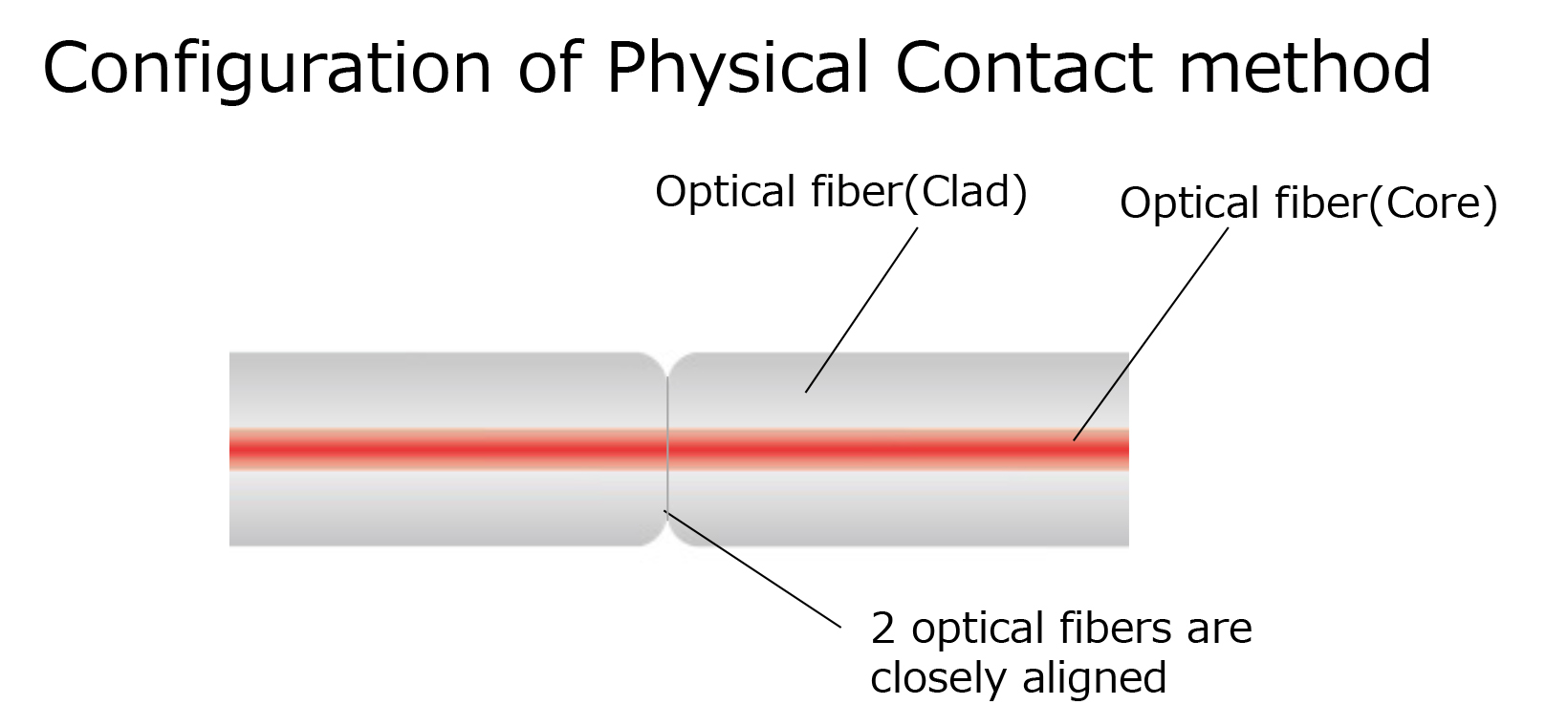
In all optical fiber connectors above, the Physical Contact method, that is a contact-type connection method, is often used for coupling between connectors and between connectors and optical communication equipment. The Physical Contact method consists of optical fibers that are placed in close contact with each other, facing each other, as shown in the figure below. Although the structure is simple, using no adhesives, etc., to mechanically adhere the parts together, high technology is required to manufacture and assemble the parts, since the accuracy of the parts directly affects the performance.
Expanded Beam optical fiber connectors
Physical Contact optical fiber connectors have several issues, one of which is resistance to dirt and foreign matter. The diameter of the communication light passing through an optical fiber is extremely thin, less than 10 um, so even a small particle of dust, etc., can block the light and cause a communication error. Another cause is scratches or damage to the tip of the optical fiber. Since optical fibers are physically in contact with each other, the tips may be scratched or damaged if excessive force is applied. The last of the issues is the strong force required for connector coupling. This is because optical fibers need to be pressed strongly against each other in order to correctly transmit and receive communication light. This issue is more pronounced with multi-fiber type connectors, because the more optical fibers are coupled, the stronger the force required. In addition, it is necessary to evenly distribute the force applied to each connector. The non-contact optical fiber connector was invented to solve these problems. The non-contact method is called the Expanded Beam method. Unlike Physical Contact connectors, Expanded Beam connectors do not tightly fit optical fibers together, leaving a gap between them. In addition, a lens is placed at the end of the optical fiber so that light can be communicated efficiently without divergence even when there is a gap between the optical fibers. There are several types of Expanded Beam optical fiber connectors, but the role of the lens can be divided into two major roles in each type: one is to expand the communication light, and the other is to convert the communication light into a collimated light so that it can reach a remote location.
Optical fiber connector with SELFOC® lens
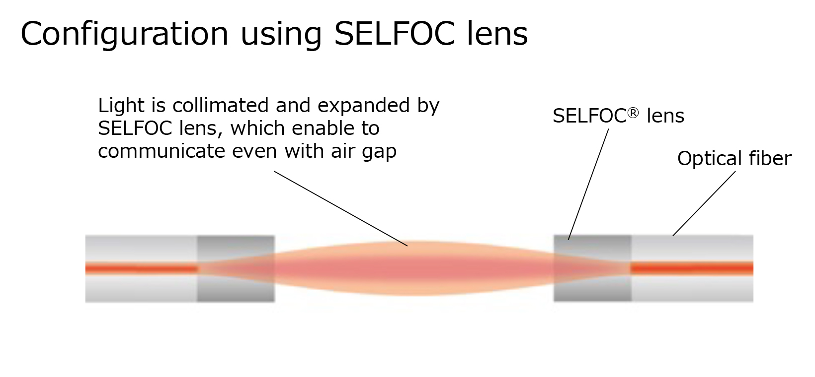
One of the lenses for Expanded Beam type optical fiber connectors is our SELFOC® lens, which is placed at the end of an optical fiber as shown in the figure below to expand and collimate the light emitted from the optical fiber.
The use of a SELFOC® lens with a diameter of only 125 um, the same as that of an optical fiber, is expected to offer advantages such as easy connection to optical fibers and miniaturization of optical fiber connectors. Other features of SELFOC® lenses include multiple NA lineups from low NA to high NA, and a wide effective range of refractive index distribution due to the absence of a cladding part, unlike ordinary optical fibers.
With the development of society and technology, it is said that the amount of information transmitted by optical communications will explode in the future, and there is a demand for more efficient and compact equipment. The SELFOC® lens technology that can meet these demands is attracting attention from many manufacturers of optical communication equipment.